
Description
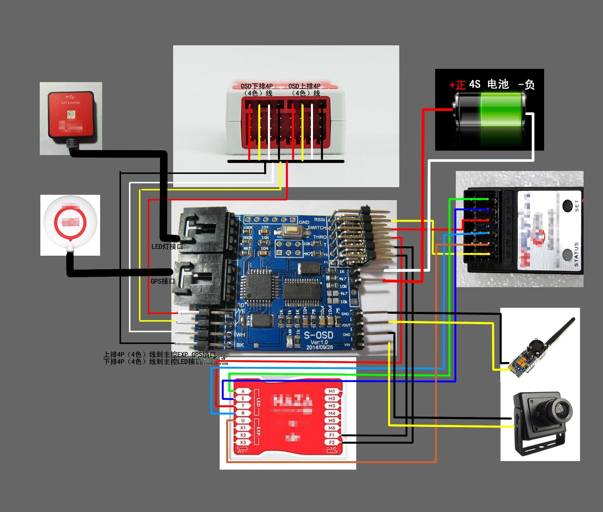
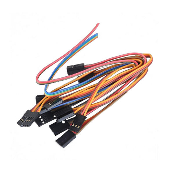
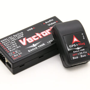
GPS Module and LED module connection:
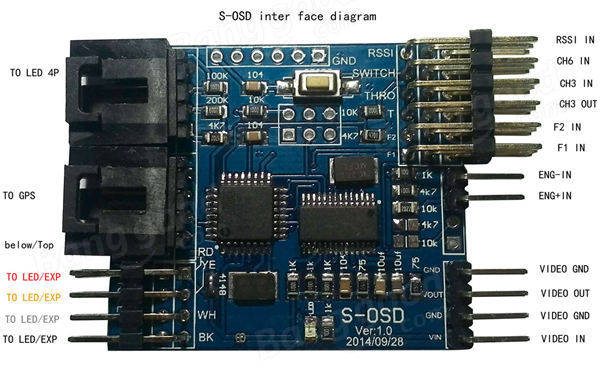
1. GPS and LED: Use 4P-4P connect main controller GPS port and LED port, supply power to flight controller. If S-OSD power light lits, then it is right.
2. Then plug GPS module and LED module at S-OSD port.
3. Switch port: The function of switch port is screen switch. There are plenty of contents S-OSD will display, so need two screens display. One time one screen content. The screen switched by transmitter 3-step switch through switch port.
4. Throttle channel: S-OSD could display throttle channel signal data from 0%-100%. Two THRO port on S-OSD, one connects receiver throttle, the other connects flight controller.
5. Attitude cable: connects with flight controller f1/f2
6. RSSI: S-OSD could display receivers signal strength, this port is used to connect receivers RSSI port
7. Voltage detection function: wiring as picture shows
8. Video port: wiring as picture shows
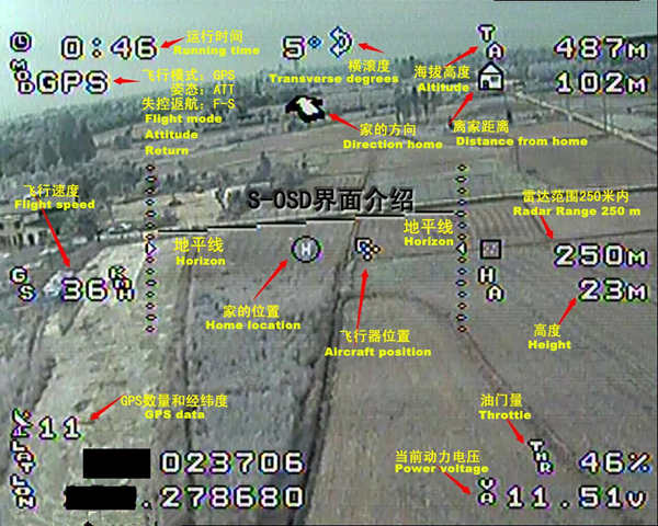
Features:
Compatible with ordinary OSD display function
Added function: Flight mode, Flight attitude, throttle channel signal data(0%-100%), receiver signal strength(if receiver with RSSI function), screen switch function(dual screen display)
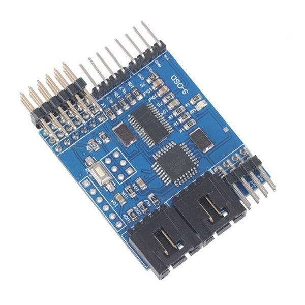
Description:
Item name: S-OSD Module
Size: 4.3cm x 3.8cm
Dynamic voltage detection: 3S-6S
Wiring Diagram


Reviews
There are no reviews yet